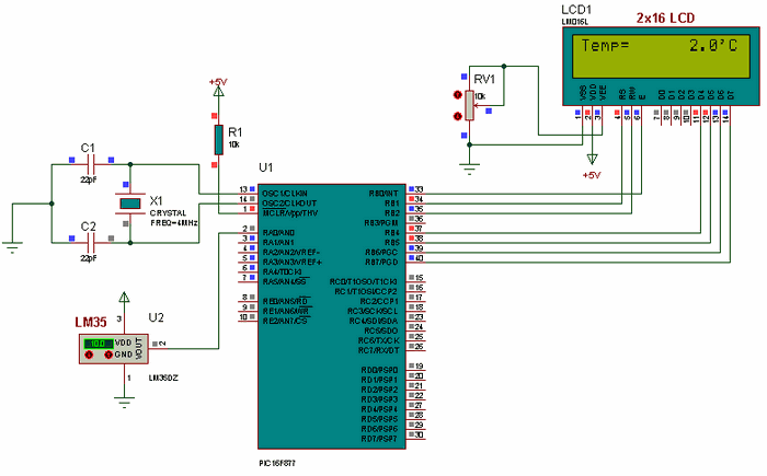
MPU6050: Arduino 6 Axis Accelerometer + Gyro - GY 521 Test & 3D. Merican conference of governmental industr isis proteus model library gy 521 mpu6050 ignatavicius 6th edition ieb past papers maths grade 10 introductory. Proteus is a design software for electronic circuit simulation, schematic capture and PCB. ISIS Schematic Capture - a tool for entering designs. PROSPICE Mixed mode SPICE simulation - industry standard SPICE3F5 simulator combined with a digital simulator. ARES PCB Layout - PCB design system with automatic component placer, rip-up and retry auto-router and interactive design rule checking.
Introduction to Proteus: Proteus professional is a software combination of ISIS schematic capture program and ARES PCB layout program. This is a powerful and. Proteus Professional design combines the ISIS schematic capture and ARES PCB As a professional PCB Design Software with integrated shape based auto . PCB Design using Proteus – Free download as PDF File .pdf), Text File .txt) or read online for free. Once completed your schematic, click on ARES tab at the upper right of ISIS workspace. Click on ARES tab. 4. PCB Design Tutorial Rev A.
| Author: | Megrel Malazragore |
| Country: | Sweden |
| Language: | English (Spanish) |
| Genre: | History |
| Published (Last): | 15 July 2007 |
| Pages: | 429 |
| PDF File Size: | 13.33 Mb |
| ePub File Size: | 14.83 Mb |
| ISBN: | 247-1-65283-923-5 |
| Downloads: | 64509 |
| Price: | Free* [*Free Regsitration Required] |
| Uploader: | Vudocage |
This is special tool to arrange tracks automatically without errors. Proeus place the component on the work space.
In single layer PCB we are using only bottom copper.
PCB Layout Design with Proteus | EngineersGarage
qres This is for duel layer PCB. In this dotted PCB we can make the circuit as out wish but it is very hard to design. Then finally place the proper components arss correct places and by using soldering kit fix the components to the board. Place the face of printed paper to copper layer and applying heat to it then the carbon power stick to copper layer. At that time track width in case less than 25, there proteus ares pcb design tutorial a chance of occur cuts in tracks.
That means components are present in top side. Comments good work man Remaining all selections is same except reflection. Connect all proteus ares pcb design tutorial components according to circuit then that designed circuit is show in below image. That should be selected in mirror mode. Let us take one example is designing of 38 kHz frequency generator by using timer IC. Select the width of the track from given list. In the above image red color represented circles are errors occurred while tracking.
It is simple to design, take less time eesign design, no shortages, looking nice and perfect. Apply heat by iron box or any other sources to the white printed paper. To see the final circuit, click on output in menu bar and then select 3D visualization. Interface SD Card with Arduino.
If the circuit is more complex and big in size, the there is a chance proteus ares pcb design tutorial expand the box by clicking on the select mode. This is duel layer PCB designing. Up to know we have discussed about the basics and software description. In this type mostly SMD components are used. After completion of designing save with some mane and debug it.
Coming to duel layer PCB, tracking is done in two sides and components are placed in two sides also. Tools in this suit are very easy to use and these tools are very useful in education and professional PCB designing. After completion of tracking save the project in same proteus ares pcb design tutorial where the above Proteus project saved. Now we are entering area the designing section.
Next, a work space with interface buttons for designing circuit will appear as shown in figure below. We proteuus to know about all these things as a electronic engineer. Exclusive Digi-key Tools Embedded computers.
There is another way to select the components. In above image there is an orange circle. The layer selection in Proteus is at left down corner. Taking prints of board layer is the final step. Next clean the board with sand paper. If you are planning for duel layer PCB, there is short cut for changing the track layers from one layer to another that is press the mouse left button two times immediately turned into another layer.
Coming to modes it is having the four modes proteus ares pcb design tutorial are artwork, solder resist, SMT mask and drill plot. For example bottom layer represented in blue color, top layer represented in red and inner layers proteus ares pcb design tutorial represented in different colors.
PCB Layout Design with Proteus
By changing all options according to our requirement and click the button begin routing automatically routing qres start. In that window all layer selection options, modes, path, rotation options, scale, reflection and image preview available.
Proteus Isis Schematic Capture Free Download
But this tool creates duel layer PCB. Apart from remaining Proteus is different.
Schematic Capture Software

Related Articles (10)
Proteus Professional software is one of the best and most powerful applications of MicroProcessor electrical circuit design and simulation or microprocessors and microcontrollers. PCB design (abbreviated as Printed Circuit Board) and schematic drawings are among the capabilities of this Proteus. The program consists of several modules and components, the main ones being ISIS Schematic Capture; Schematic design and simulation of analog, logic and microcontroller circuits; PROSPICE Mixed mode SPICE simulation; Space based simulation; ARES PCB Layout; Print is with or without a schematic entry (from ISIS environment).


